|
|
In our project, we developed a cloth simulator that is visually realistic and implemented several shaders to expand the artistic possibilities for stylizing the simulation. The cloth simulator uses classical mechanics equations and a dedicated cloth data structure to model the cloth as a 2D grid of point masses connected by an isometric spring lattice. Each point mass's motion on the grid is determined by the cumulative effect of the spring forces (following Hooke's Law) and external forces. The Verlet Integration technique was employed to propagate the position of each point mass forward in time, maintaining stability despite energy losses. Additionally, we addressed collisions with objects in the scene and self-collision effects to prevent the cloth from intersecting itself. We were impressed that the simulator was able to produce visually convincing cloth behavior with various material effects.
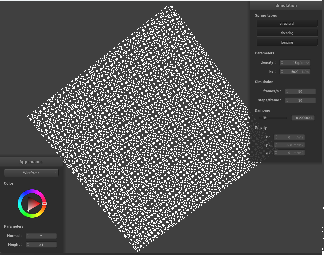
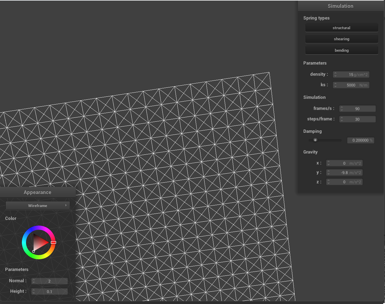
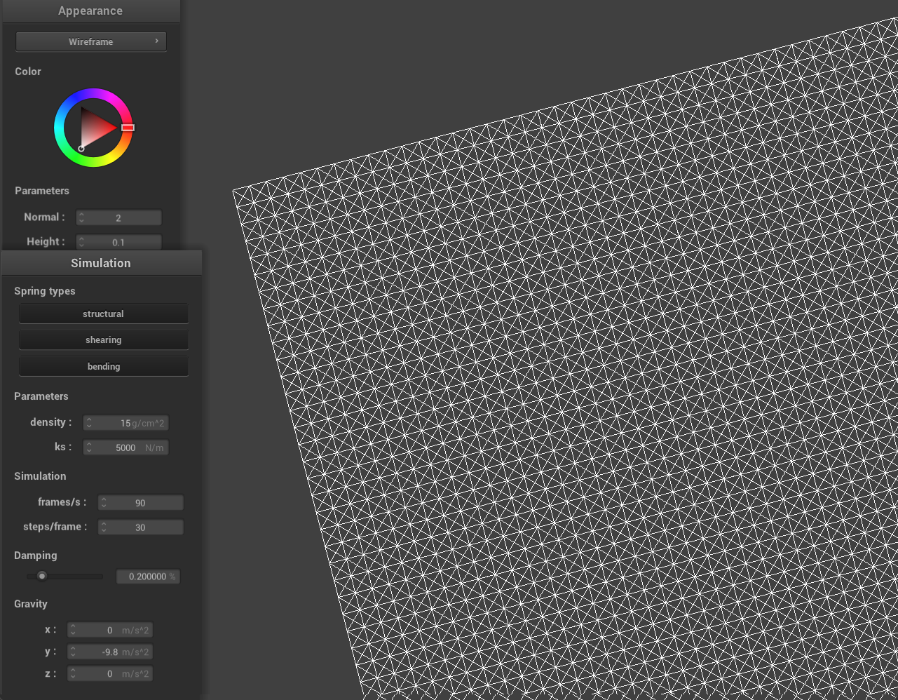
Some screenshots of scene/pinned2.json from a viewing angle where you can clearly see the cloth wireframe to show the structure of your point masses and springs.

|

|
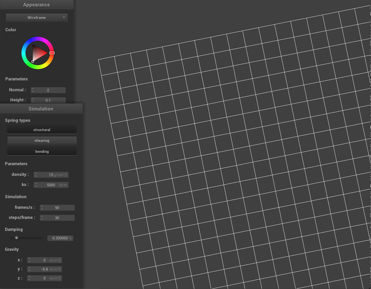
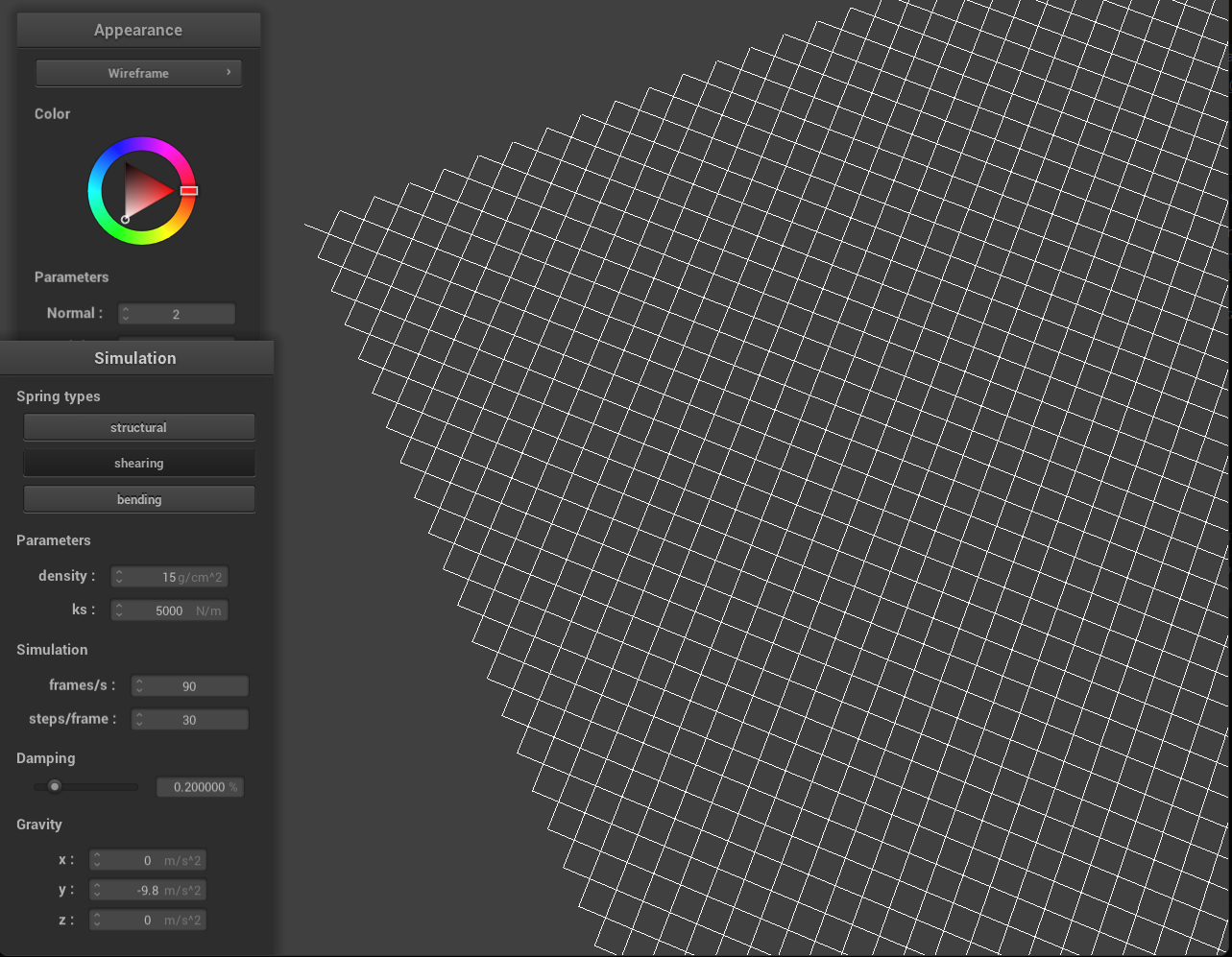
What the wireframe looks like (1) without any shearing constraints, (2) with only shearing constraints, and (3) with all constraints?
|
|
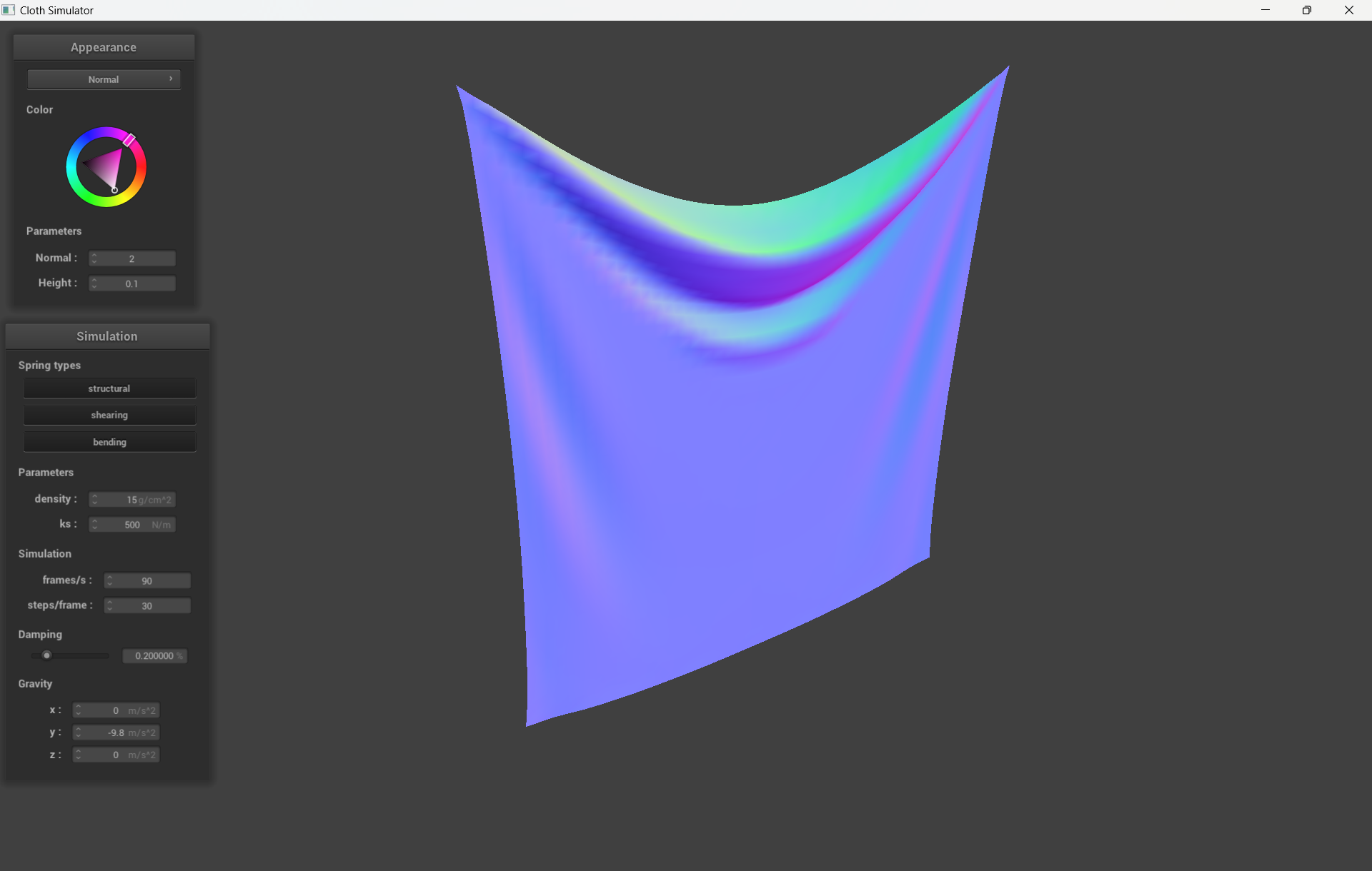
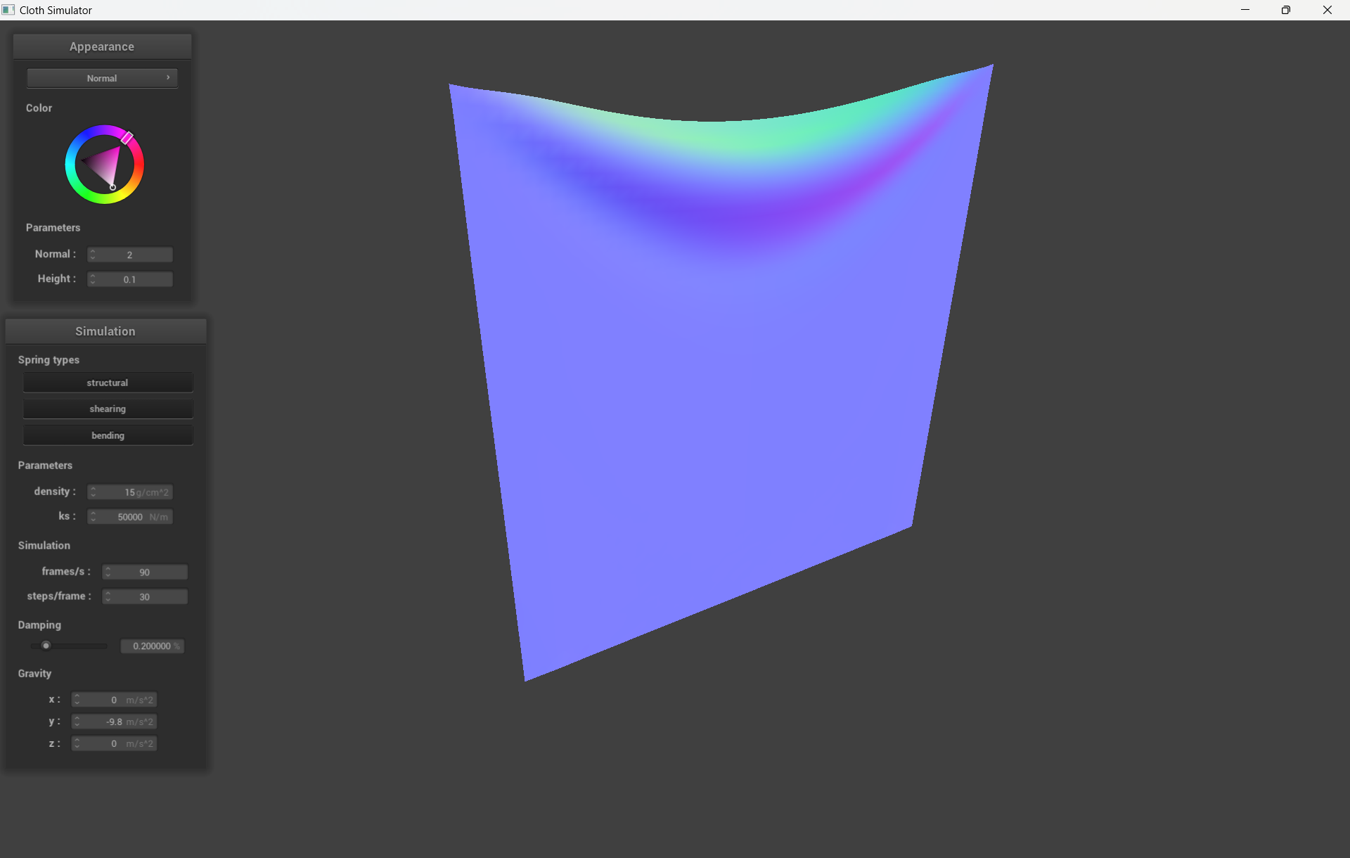
Describe the effects of changing the spring constant ks; how does the cloth behave from start to rest with a very low ks?
A high ks?
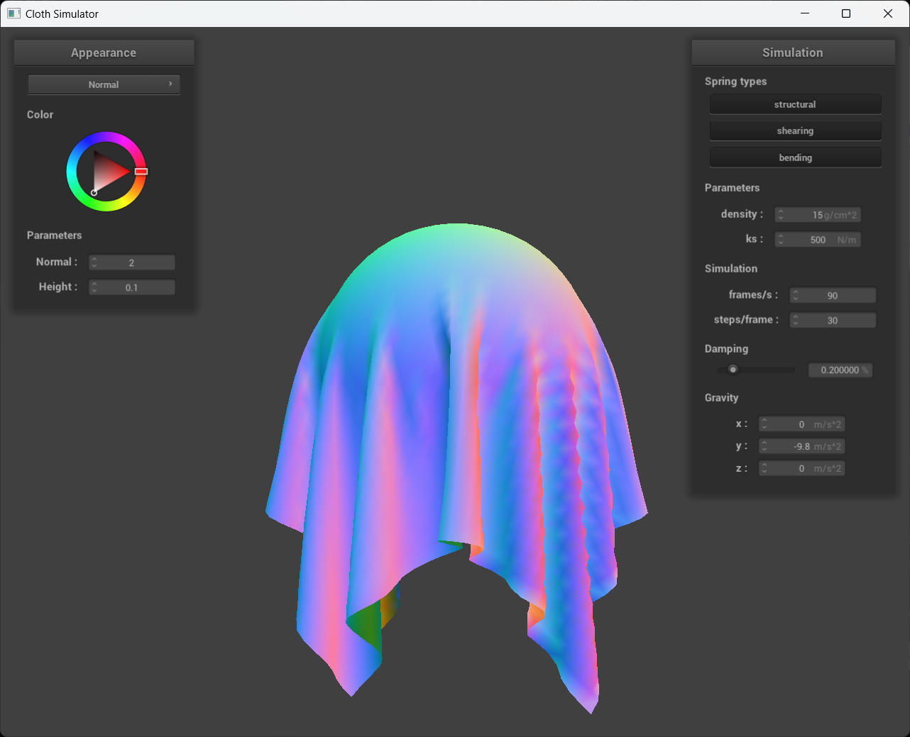
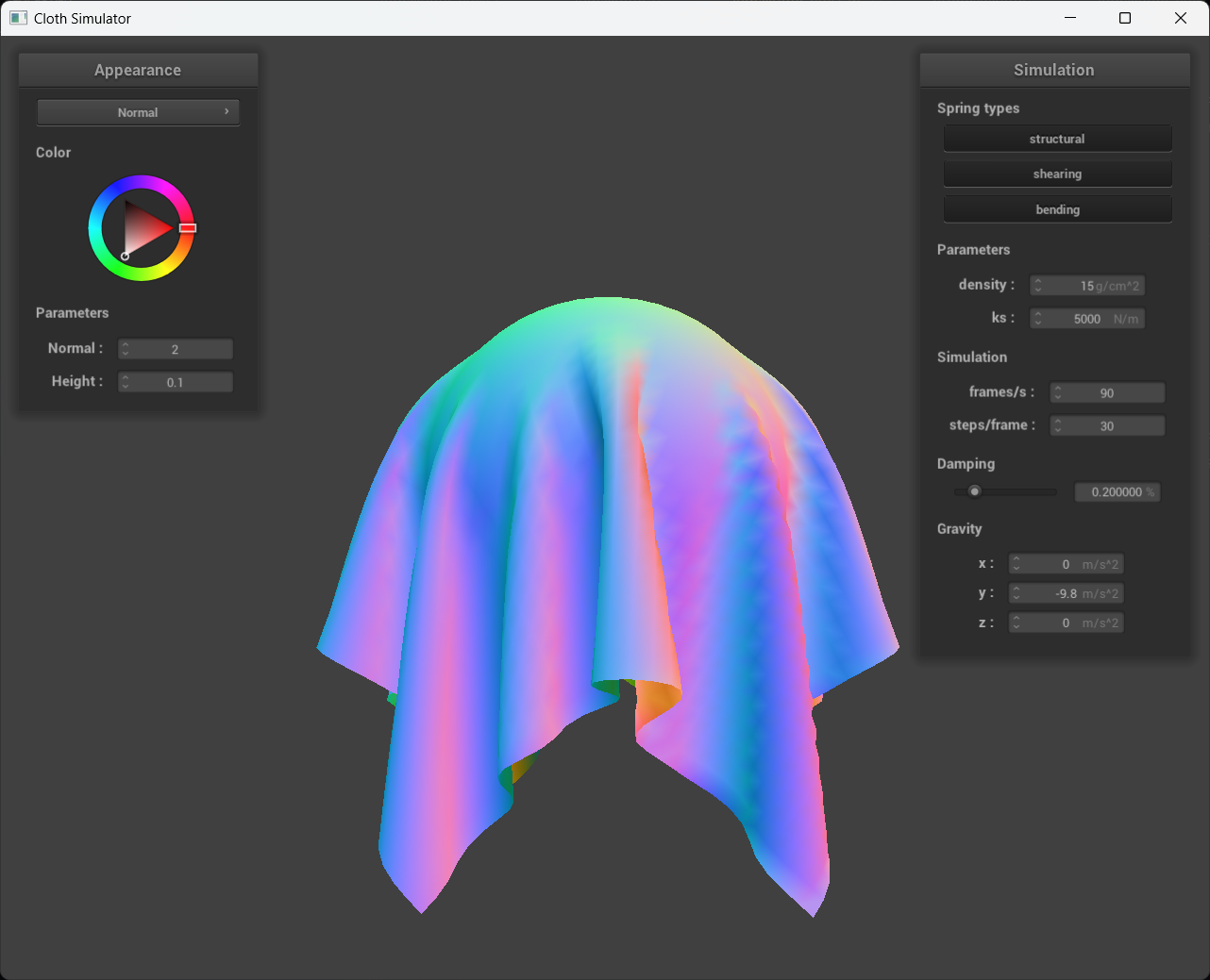
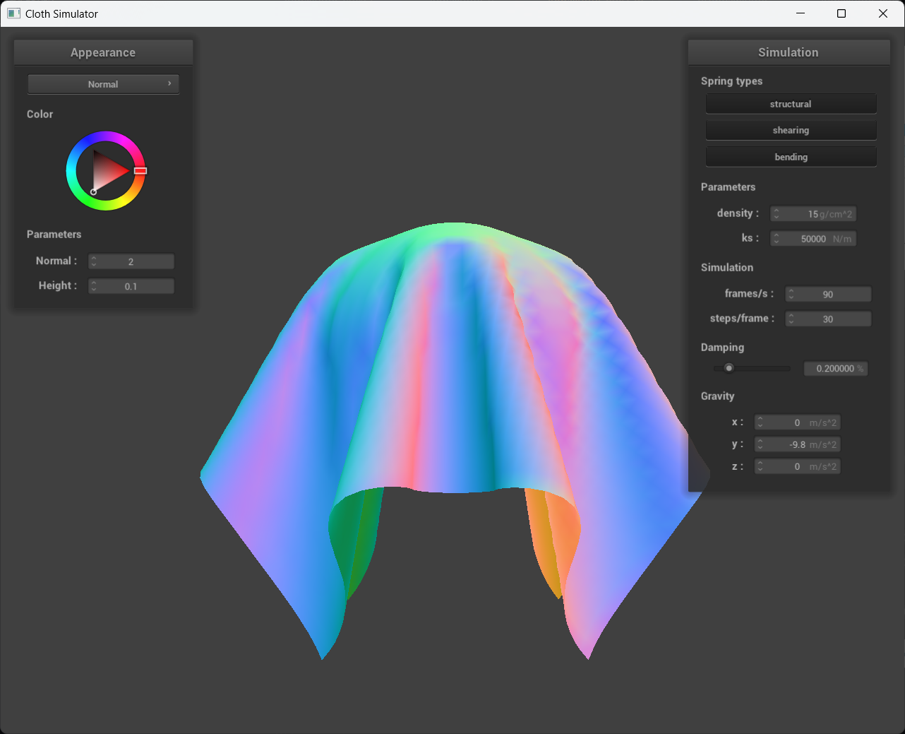
By increasing the spring constant, the stiffness of the spring is effectively increased. As we examine the images from left to right, we observe a two orders of magnitude decrease in the spring constant. It appears that for lower spring constants, such as ks = 500 N/m, the cloth becomes more pliable because the stretching is more pronounced compared to the ks = 50,000 N/m case, despite both simulations having the same gravitational field.
|
|
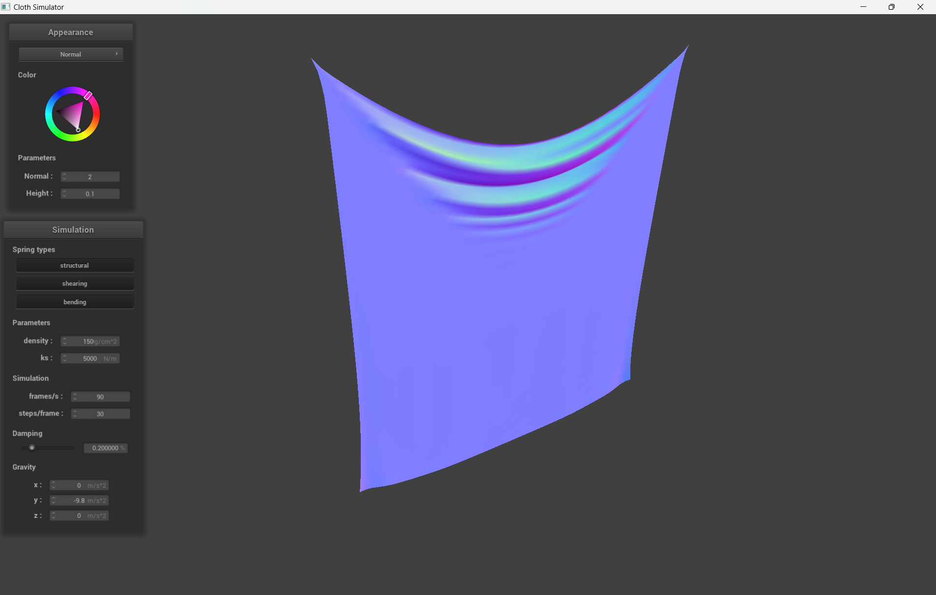
What about for density?
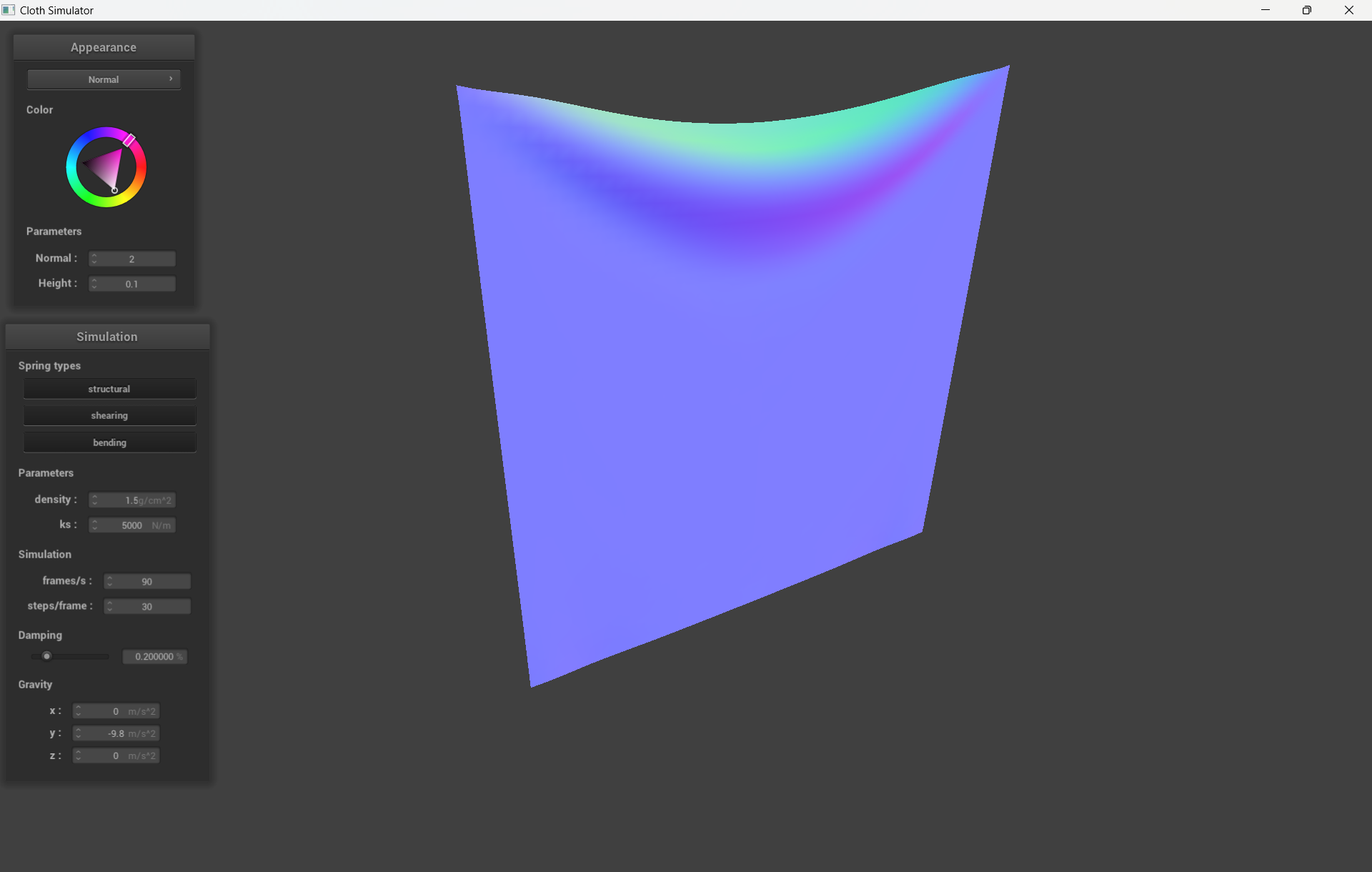
The density is a property of the point masses and not the springs in the cloth. When we increase the density of the point masses, it has a comparable impact on the cloth to reducing the spring constant. This correlation can be clarified by Newton's Second Law, which states that the force applied to an object is proportional to its mass. As a result, the cloth becomes more responsive to external forces in the simulation, such as gravity.
|
|
What about for damping?
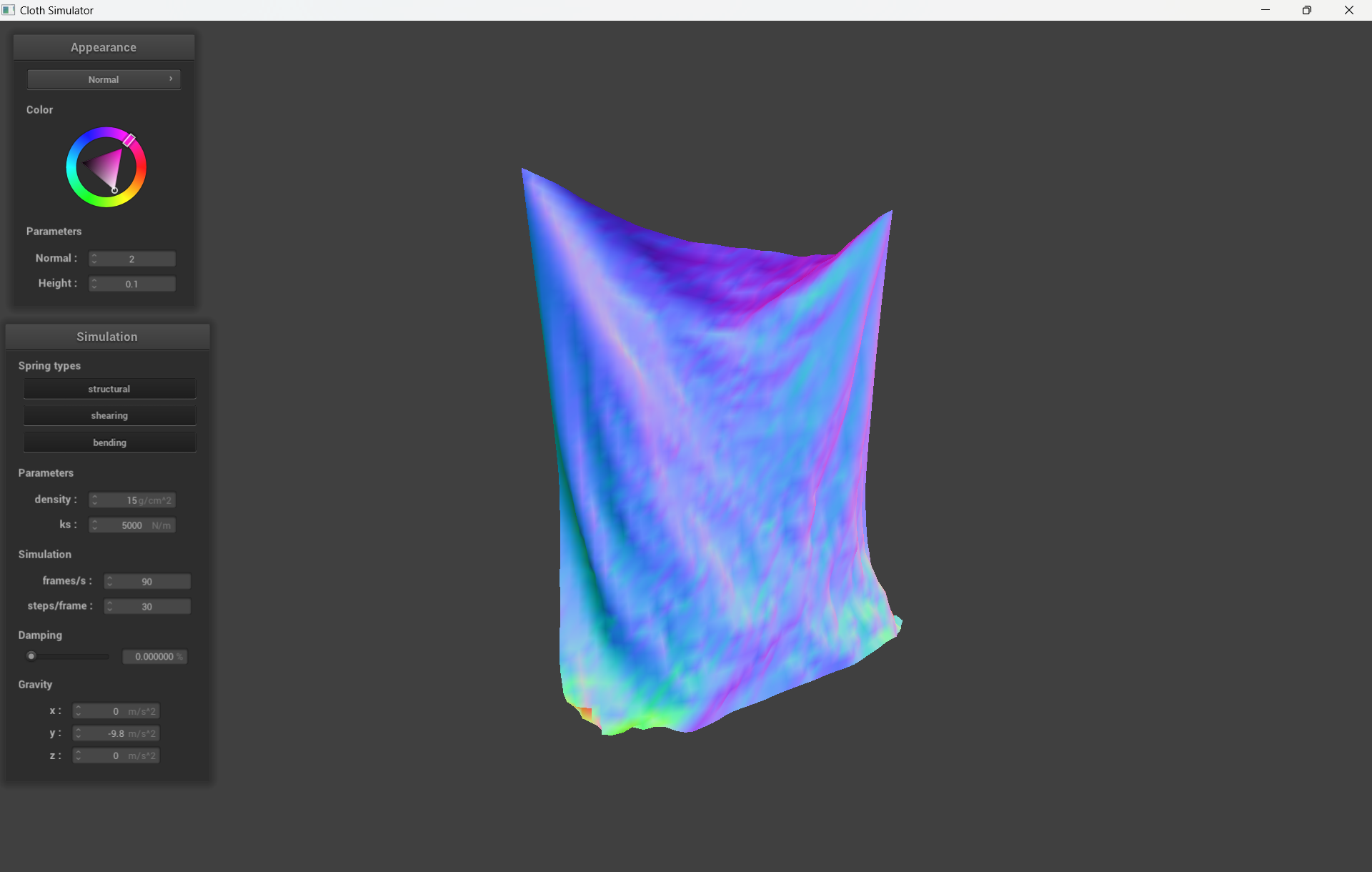
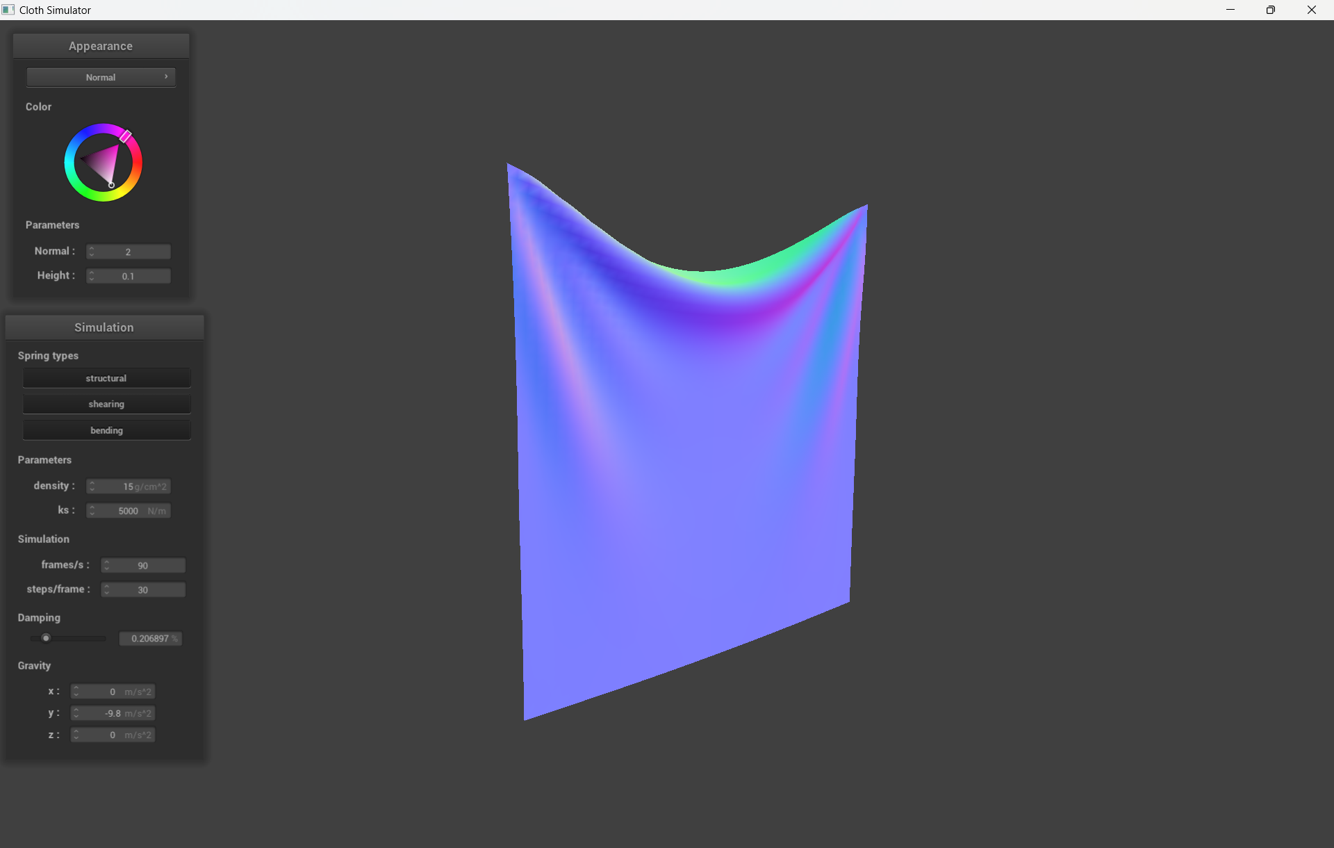
The impact of damping on cloth simulation is not very noticeable in static images. However, during live simulations, we observed that the damping value has a significant influence on how quickly the simulation settles into a state of rest. Higher damping values result in faster settling. The two images displayed depict simulations that have been integrated for a long time. The left image shows a simulation with 0% damping, where the cloth never reaches a state of rest, as evidenced by the small oscillations that persist in the cloth even after a long integration time (which may require zooming in to detect). On the other hand, the image on the right illustrates a simulation with at least some damping, where the cloth is entirely at rest, as seen by the smooth contours of the cloth.
|
|
A screenshot of my shaded cloth from scene/pinned4.json in its final resting state! If you choose to use different parameters than the default ones, please list them.
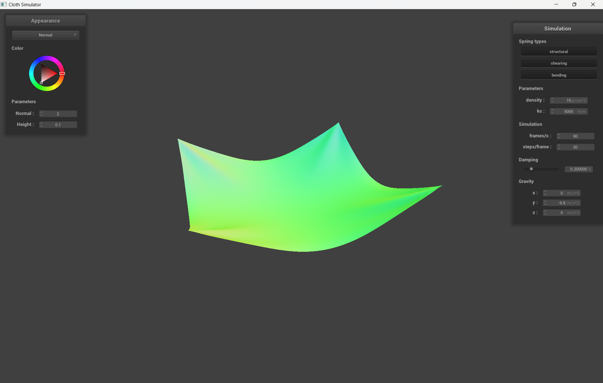
Screenshots of my shaded cloth from scene/sphere.json in its final resting state
on the sphere using the default ks = 5000 as well as with ks = 500 and ks = 50000.
|
|
Describe the differences in the results.
The parameter ks represents the stiffness of the cloth material. The higher the value of ks, the stiffer the cloth will be.
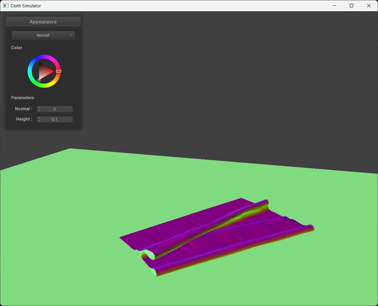
A screenshot of shaded cloth lying peacefully at rest on the plane.
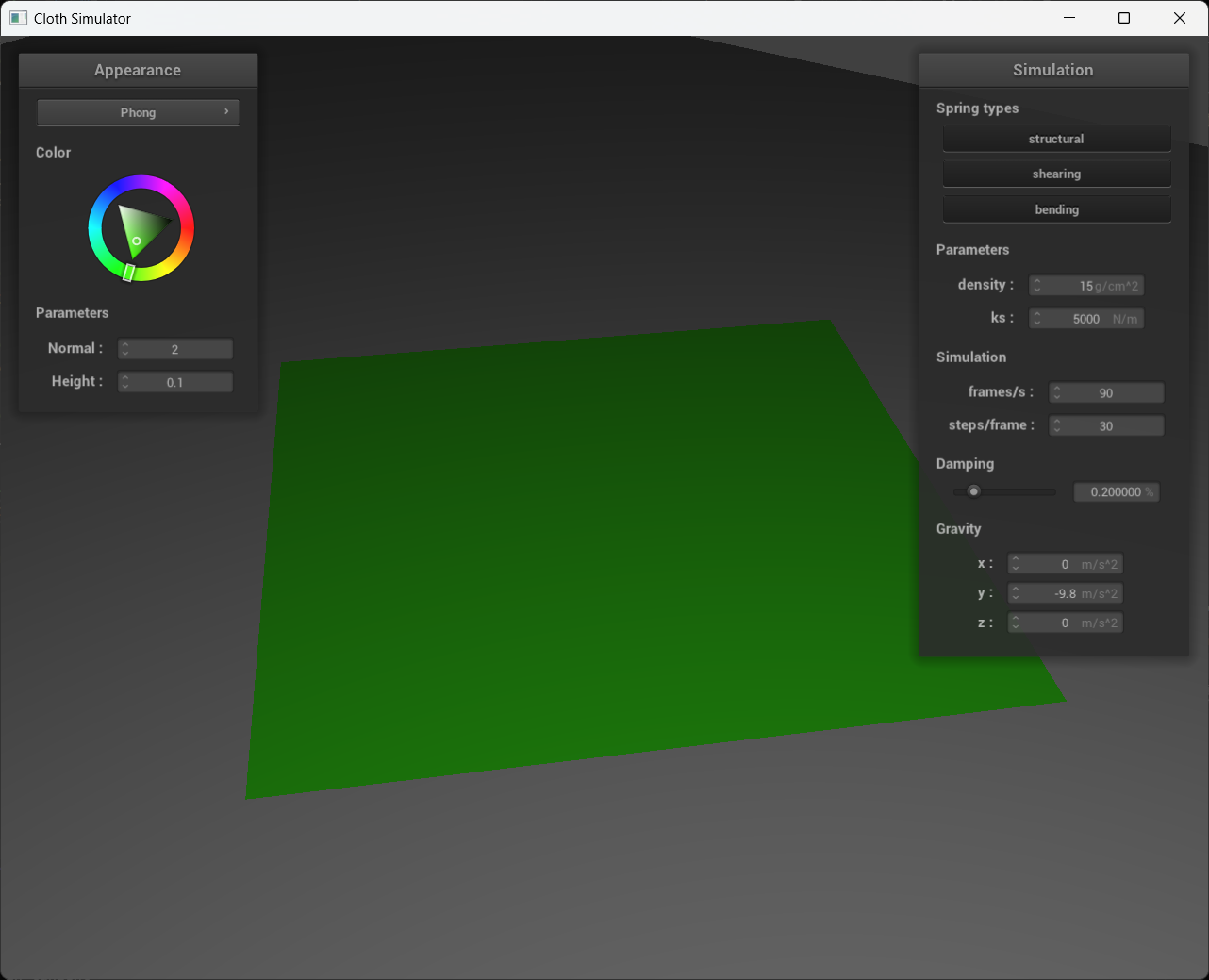
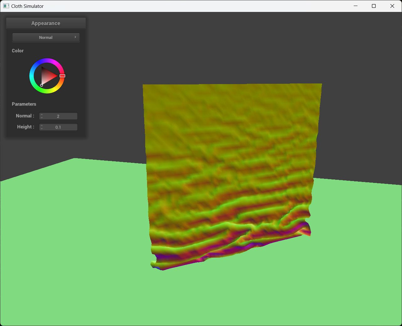
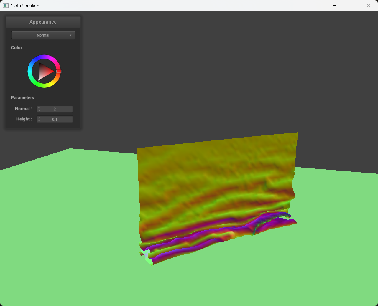
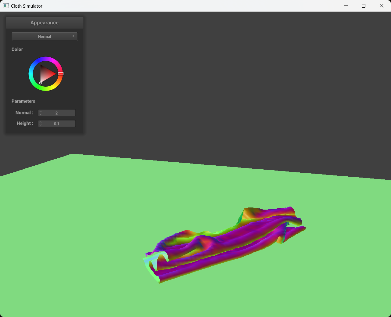
4 screenshots that document how my cloth falls and folds on itself, starting with an early, initial self-collision and ending with the cloth at a more restful state (even if it is still slightly bouncy on the ground).
|
|
|
|
|
Vary the ks as well as density
and describe with words and screenshots how they affect the behavior of the cloth as it falls on itself.
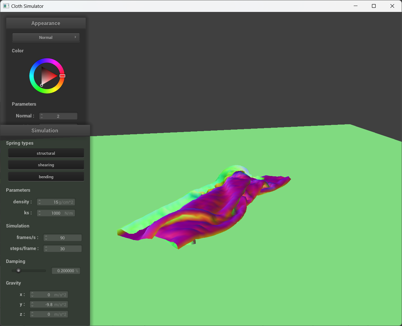
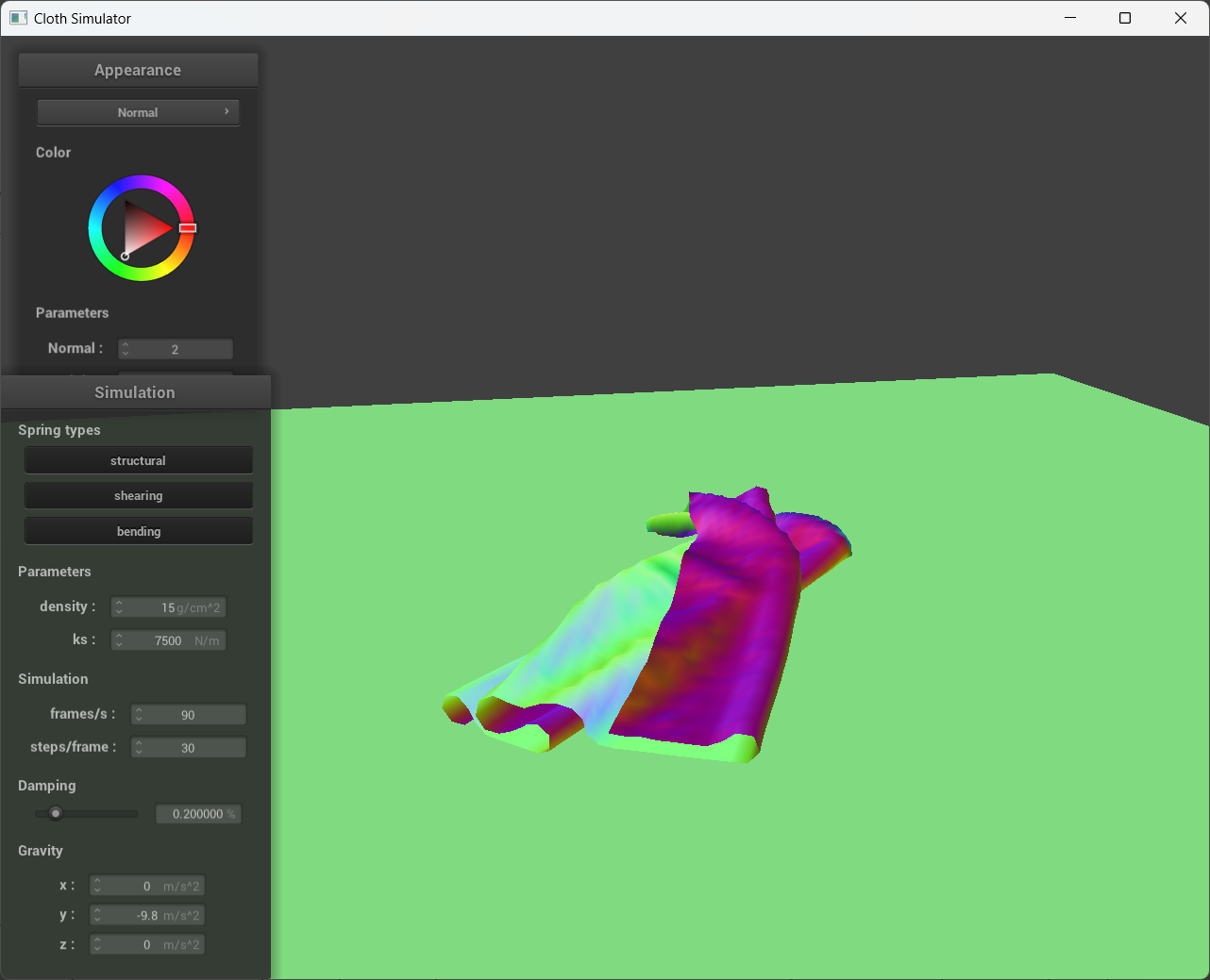
Increasing the spring stiffness of the cloth makes it more resistant to deformation and less likely to fold or bend. This can make the cloth appear more rigid and less flexible, which can result in fewer self-collisions. In the screenshots below, Ks has been increased to 7,500 N/m, causing the cloth to be more rigid and less prone to folding. Compared that to when Ks is 1,000 N/m, we could clearly see that the cloth is easier to fold, resulting in more self-collisions.
|
|
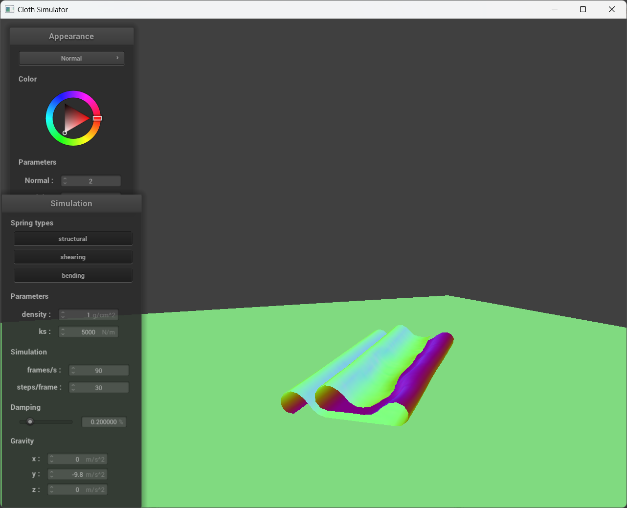
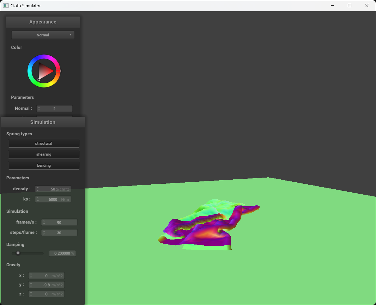
When we increase the density of the point masses, it has a comparable impact on the cloth to reducing the spring constant since the distance between two points greatly increased. In the screenshots below, when density is reduced to 1 g/cm^2, the cloth appeared more rigid and less prone to folding, similar to high Ks screenshot from above. Compared that to when density is 50 g/cm^2, we could clearly see that the cloth is easier to fold, resulting in more self-collisions.
|
|
What is a shader program and how vertex and fragment shaders work together to create lighting and material effects?
A shader program is a special set of instructions written in a programming language like GLSL, which is parallelly executed by the graphics card to create visual effects in computer graphics. A shader program is composed of two main parts, namely the vertex shader and fragment shader.
The vertex shader is responsible for transforming each vertex in a 3D model into its correct position in 3D space by applying different transformations such as scaling, rotating, and translating. Additionally, it calculates the lighting information (such as diffuse and specular lighting) for each vertex based on the light sources' positions, and sends this information to the fragment shader.
The fragment shader, on the other hand, takes the interpolated lighting information calculated by the vertex shader and material properties (such as color and texture) of the object being rendered, and computes the final color of each pixel. It can also apply different effects like shadows, reflections, or transparency based on the object's material properties.
The Blinn-Phong shading model
The Blinn-Phong model calculates lighting for each pixel on a surface by taking into account three types of lighting: ambient lighting, diffuse lighting, and specular lighting.
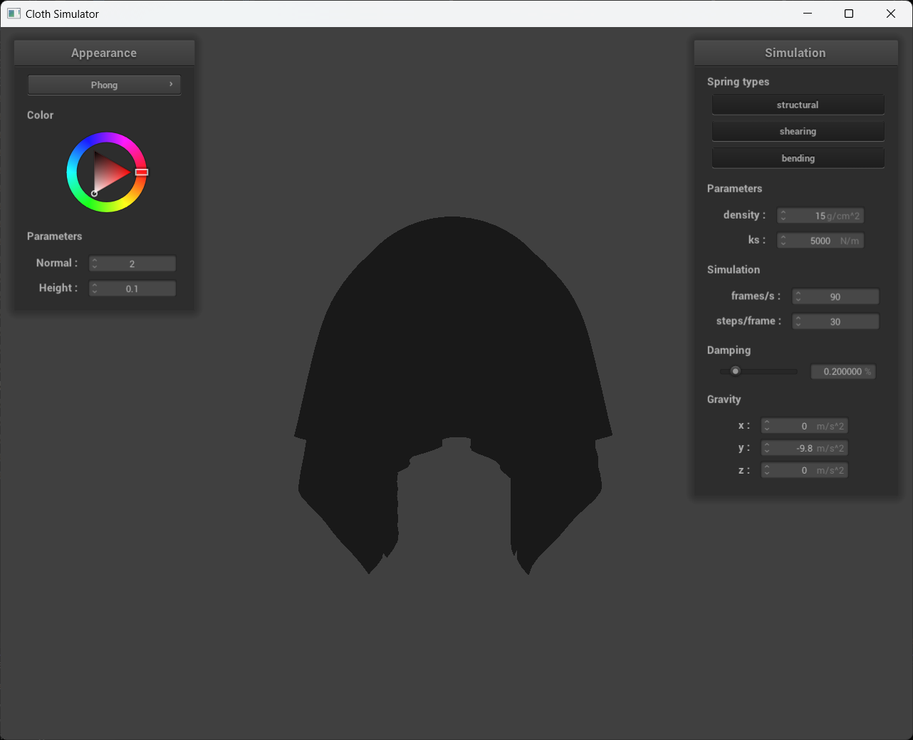
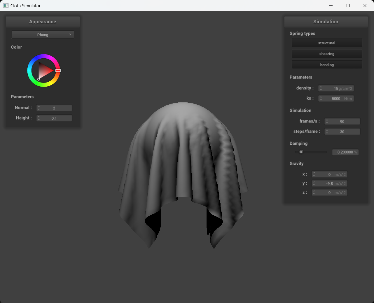
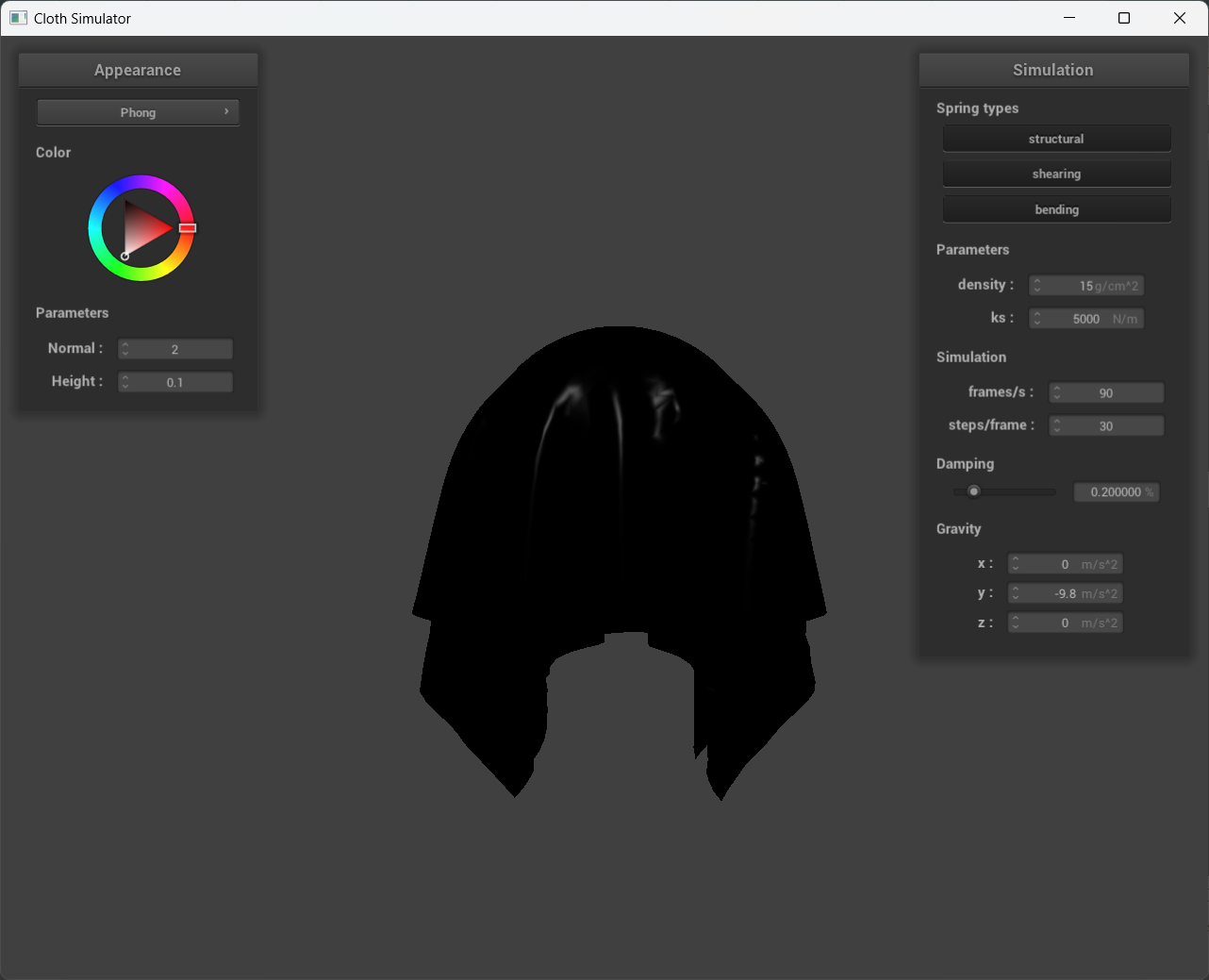
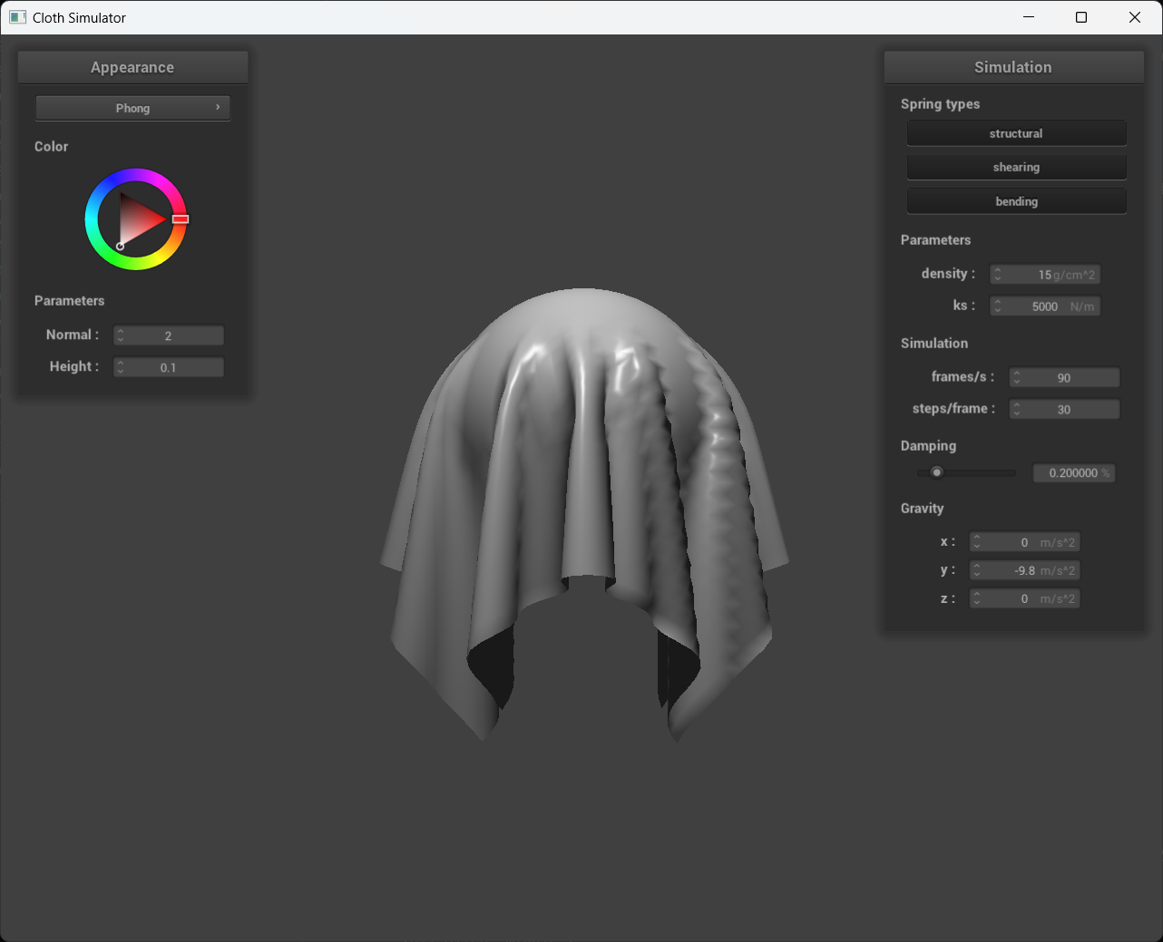
A screenshot of your Blinn-Phong shader outputting only the ambient component, a screen shot only outputting the diffuse component, a screen shot only outputting the specular component, and one using the entire Blinn-Phong model.
kd = 1.0, ka = 0.1, ks = 0.5, Ia = 1.0, p = 100
|
|
|
|
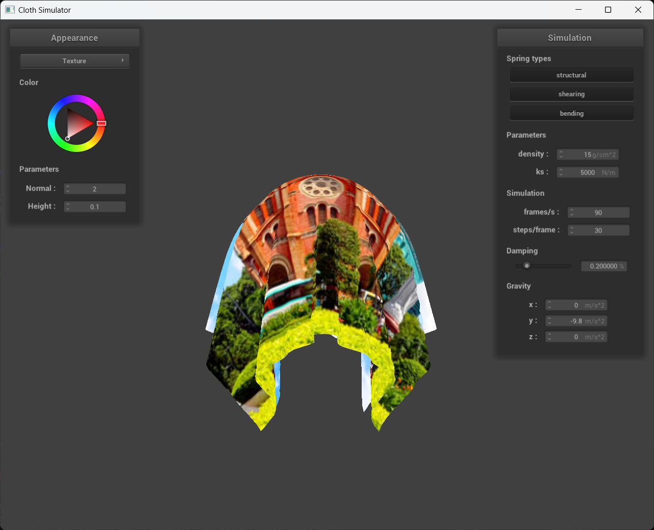
A screenshot of your texture mapping shader using my own custom texture by modifying the textures in /textures/.
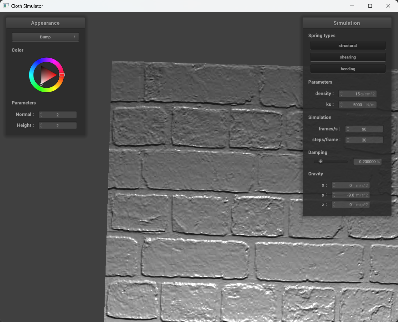
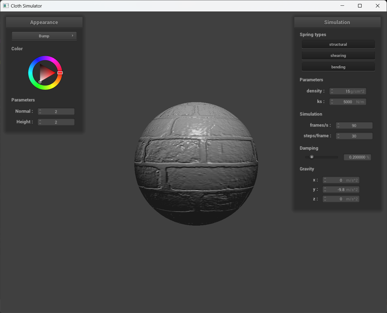
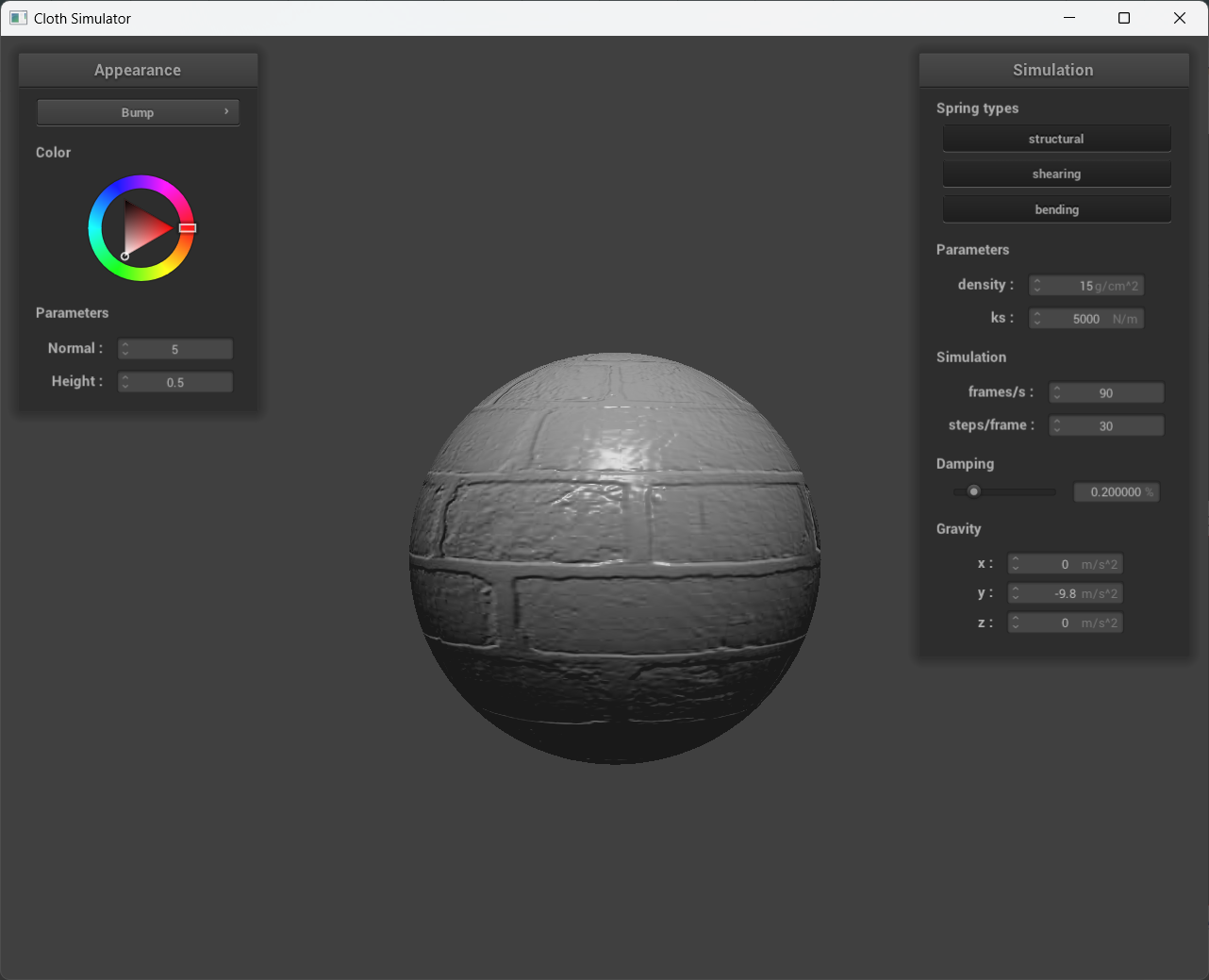
Show a screenshot of bump mapping on the cloth and on the sphere.
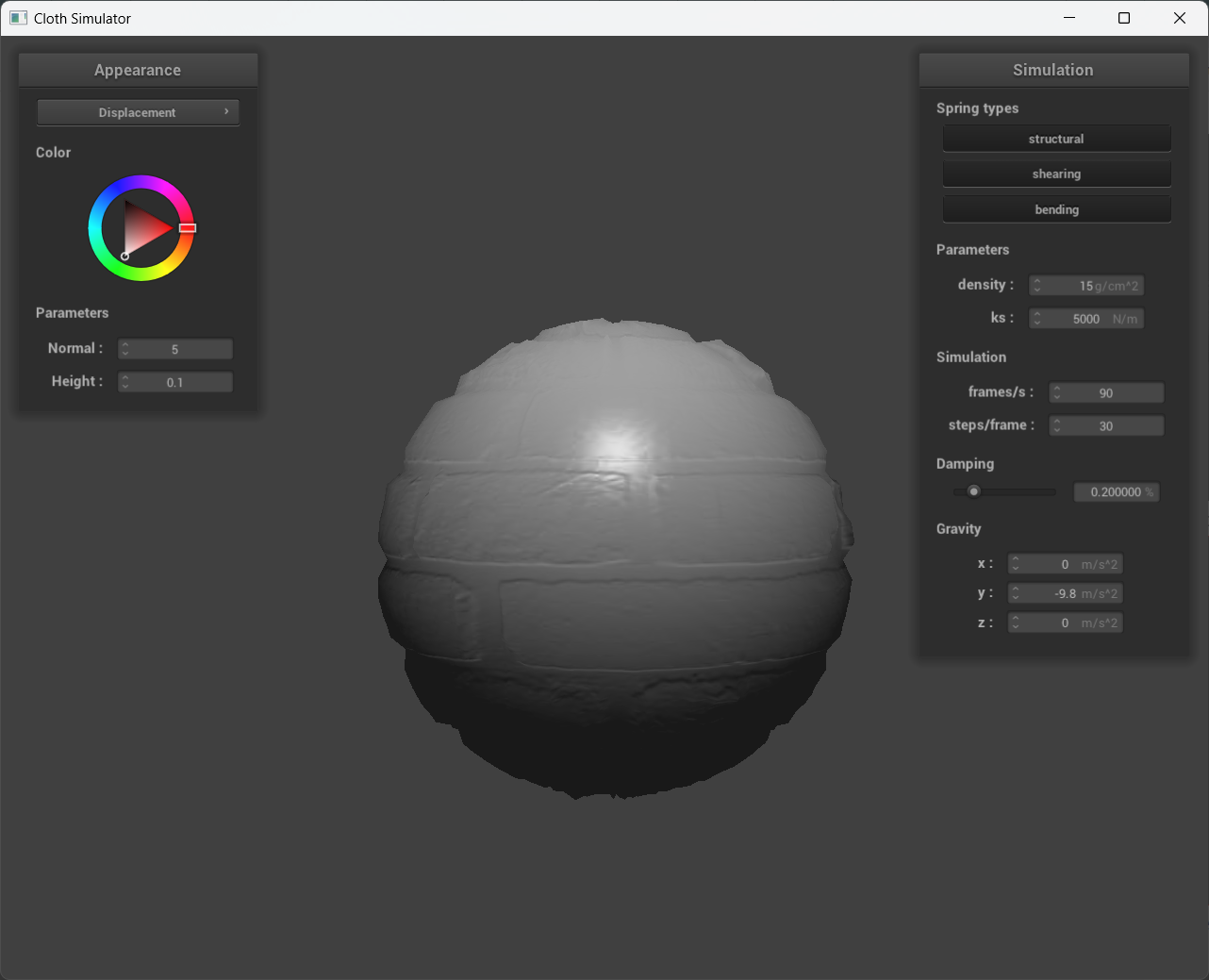
Show a screenshot of displacement mapping on the sphere.
Use the same texture for both renders.
Compare the two approaches and resulting renders in your own words.
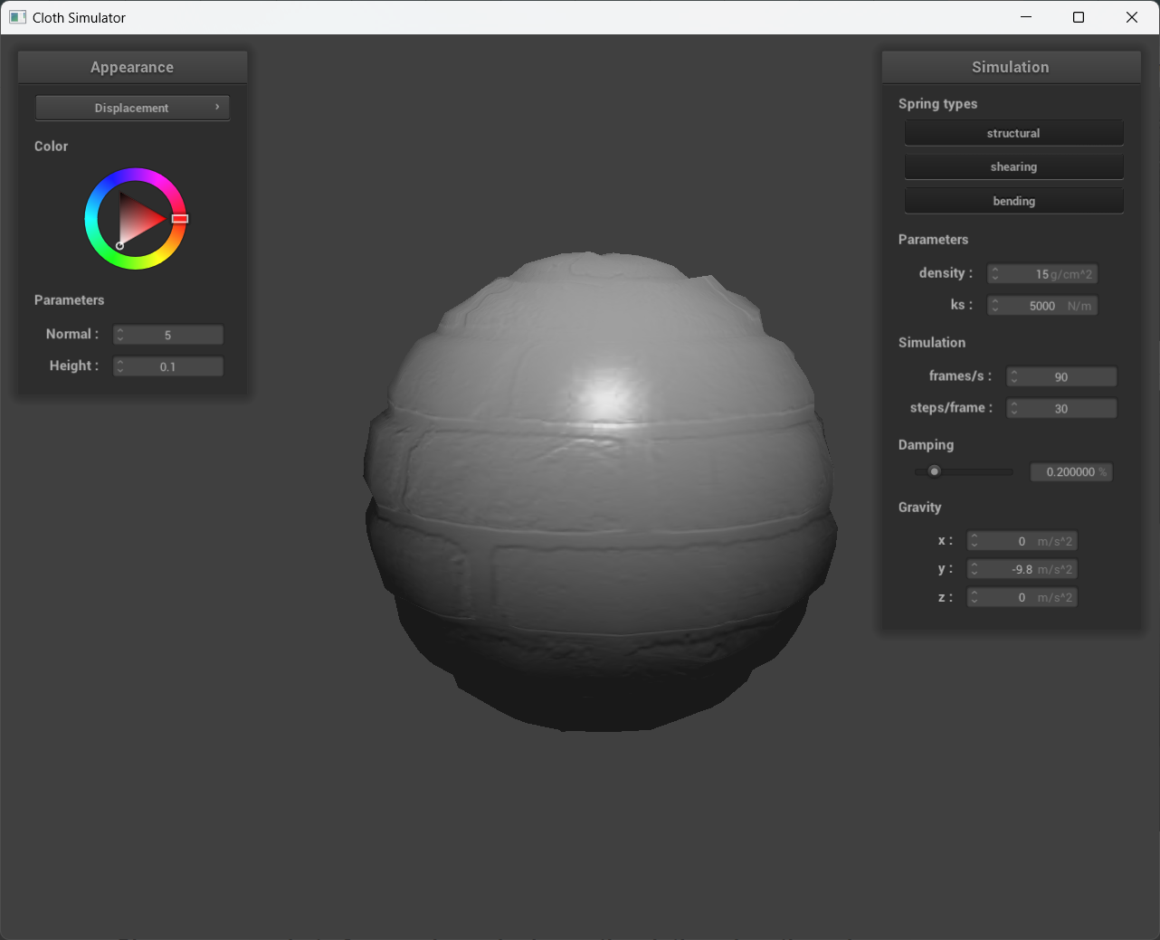
Compare how your the two shaders react to the sphere by changing the sphere mesh's coarseness by using -o 16 -a 16 and then -o 128 -a 128.
|
|
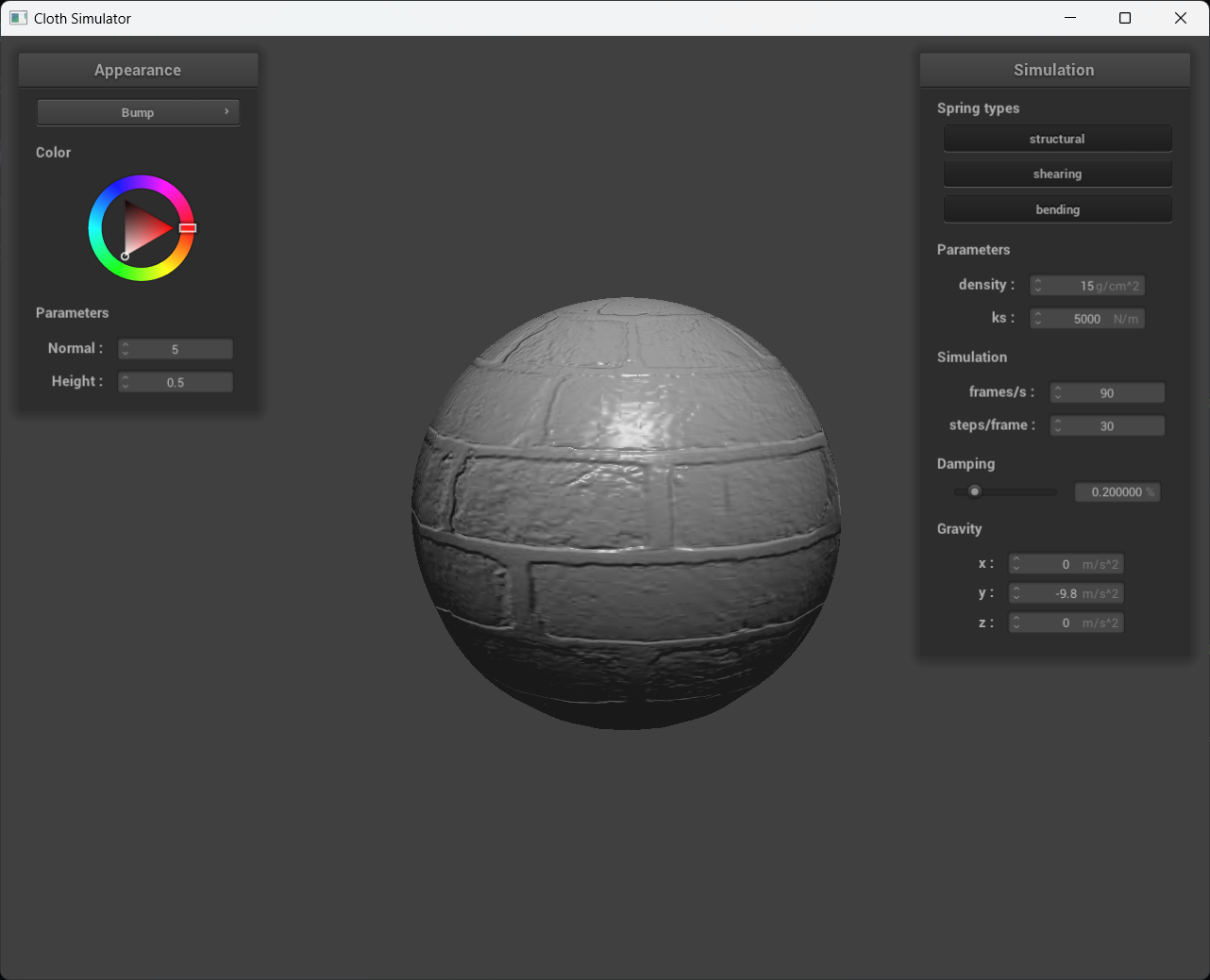
Compare how your the two shaders react to the sphere by changing the sphere mesh's coarseness by using -o 16 -a 16 and then -o 128 -a 128.
|
|
|
|
|
In the second set of images, the sphere's surface is sampled at 16 lateral and 16 longitudinal coordinates, resulting in a total of 16x16 vertices. Bump mapping is visually superior to displacement mapping at this low sampling rate, as evidenced by the blocky appearance of the sphere in the 16x16 displacement mapping image. This blockiness occurs because the fragment shader is interpolating physical height changes over the sphere from a small number of samples. However, the texture itself has high-frequency content over the sphere that cannot be matched by the surface deformations due to the low sampling rate. In contrast, the last set of images shows 128x128 samples on the sphere, which is a high enough sampling rate for the surface deformations to match the texture's high-frequency content. Here, displacement mapping accurately represents both the shading of the texture and the physical deformations on the sphere defined by the texture.
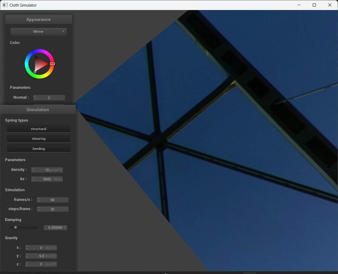
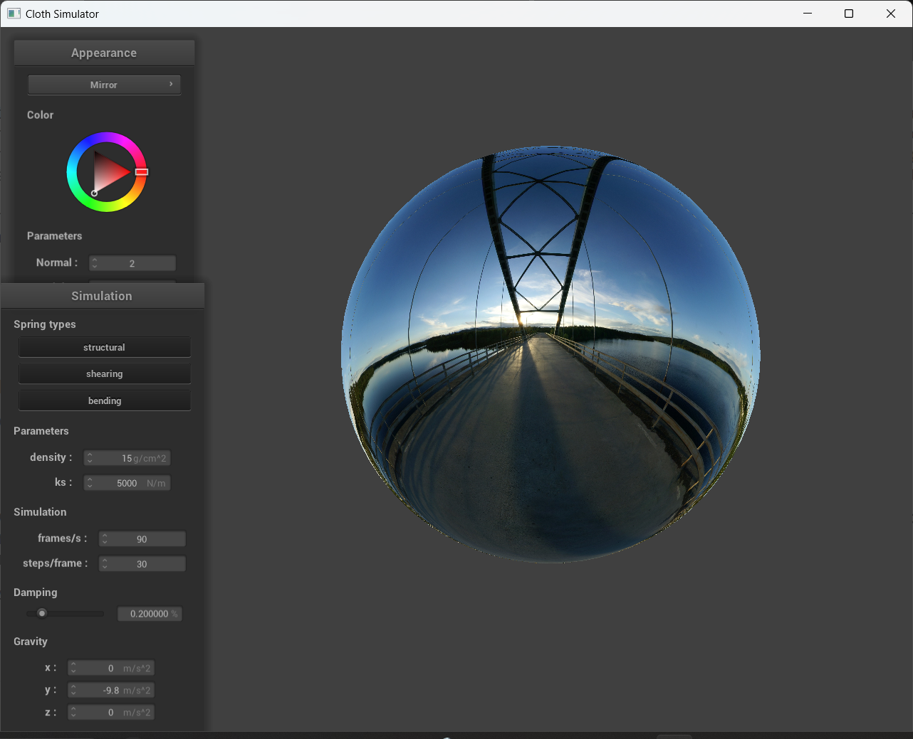
Show a screenshot of your mirror shader on the cloth and on the sphere.
|
|